
How to install: Inlet temperature sensor
How to install the inlet temperature sensor on your ROEST.
Sections:
Where to buy an inlet temperature sensor?
The inlet temperature sensor will be available to buy in January.
Before you start
⚠️DISCLAIMER
Information in this document is believed to be accurate and reliable. However, the manufacturer does not give any representations or warranties, expressed or implied, as to the accuracy or completeness of such information and shall have no liability for the consequences of the use of such information. The manufacturer is not liable or responsible for any problems arising from the attempted repair. The manufacturer reserves the right to make changes to information published in this document, including without limitation specifications and product descriptions, at any time and without notice. The manufacturer's products are not designed, authorized, or warranted to be suitable for use in applications where failure or malfunction can reasonably be expected to result in personal injury, death, or severe property or environmental damage. The manufacturer accepts no liability for inclusion and/or use of its products in such equipment or applications, and therefore such inclusion and/or use is for the customer’s own risk.
⚠️SAFETY INSTRUCTIONS
make sure the roaster is turned off
the power cord has to be unplugged
follow the steps as instructed below
Tools
2.5-millimeter hexagonal key (L or T-shaped)
Scissors
Slotted screwdriver 2-millimeter
Included parts
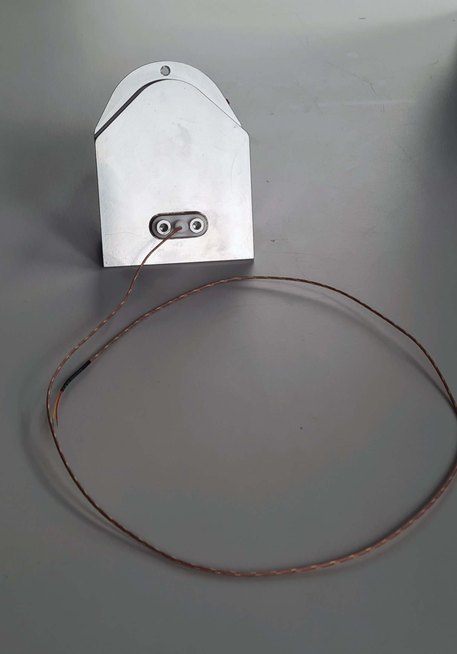
Your inlet temperature sensor part.
Inlet temperature installed into the heating element housing
Cable ties
Aluminum tape
3-millimeter hexagonal key (long L-shaped)
Instructions
2. Remove the right-hand side panel.
3. Take off the front décor plate.
4. Only for L100, remove the k-type cable from the PCB.


When you remove the drum temp sensor, leave the connector wide open. The connector on the right is in the correct position, and the connector on the left is in the wrong position.
5. Disconnect the heater fan from the PCB and cut the cable ties holding the cables from the heater fan in place.


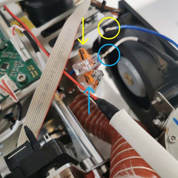
6. Disconnect the heating element cables from the wago connectors. Undo the two screws on the heating element lid with a 2.5-millimeter hex key, and lift the heating element away from the housing. Put it aside. NOTE: Before disconnecting, take a photo or make a reference to ensure that the correct cable goes into the correct wago connector when reconnecting. Remove the silicone hose.
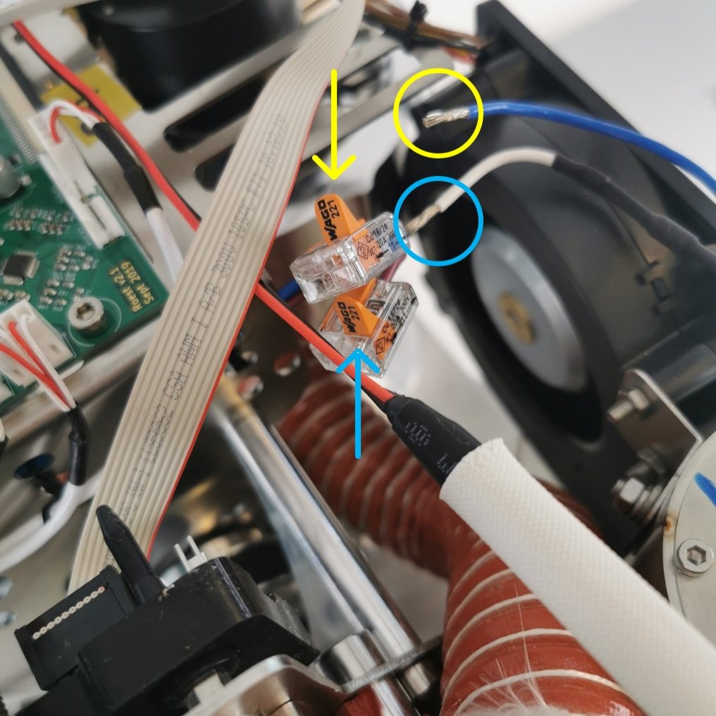
Only open the two flaps that read Wago 221.

7. Remove the four cap head bolts holding the heater fan with the 3-millimeter hexagonal tool.

Two located at the front of the roaster

And another two located at the back.
8. Remove the two cap head bolts holding the super wool bracket using the 3-millimeter hexagonal tool.

One bolt is located at the front

And the other two is located inside the roaster, right below the screws holding the blower fan in place (step 6).
8. Remove the superwool bracket and the superwool.

Superwool and bracket
10. Remove the old heater fan assembly. To do this safely and correctly, follow these steps:

1. Push the heating element housing towards the drum (this will tilt the assembly at approximately 45˚).

2. Pull the heater fan assembly out while maintaining the 45˚ angle. Pull the drum temperature sensor cable out from the holes in the heater fan.
11. Remove the big piece of super wool now visible with the heater fan removed.

12. Cut the big piece of super wool at the angle where it bends. Then place the smaller piece close to the drum using a tool to push down the wool, so it doesn’t cover the holes.

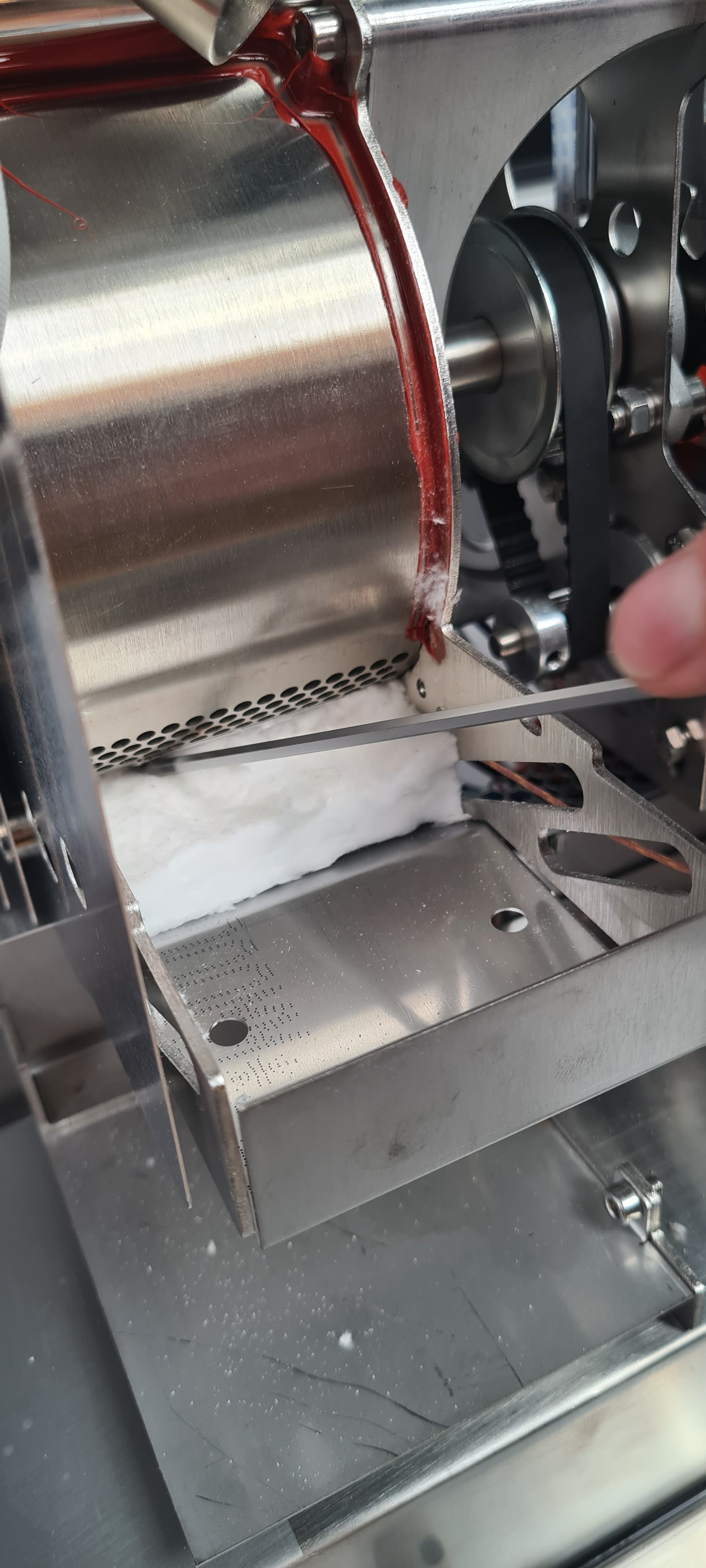

Incorrect: The super wool shouldn’t cover the holes like in the photo above.
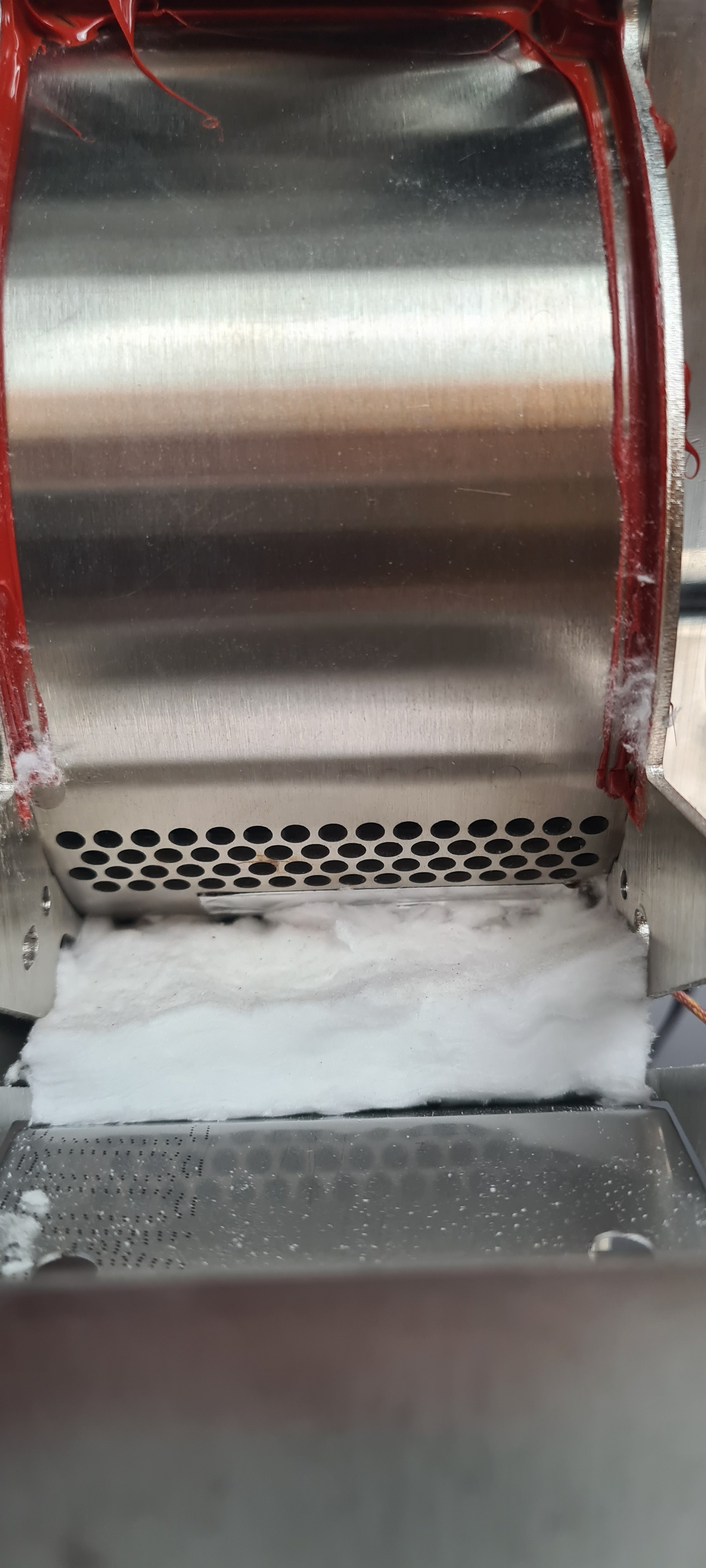
Correct placement of super wool.
13. Remove the housing for the heating element.

Undo the two bolts on the lid.

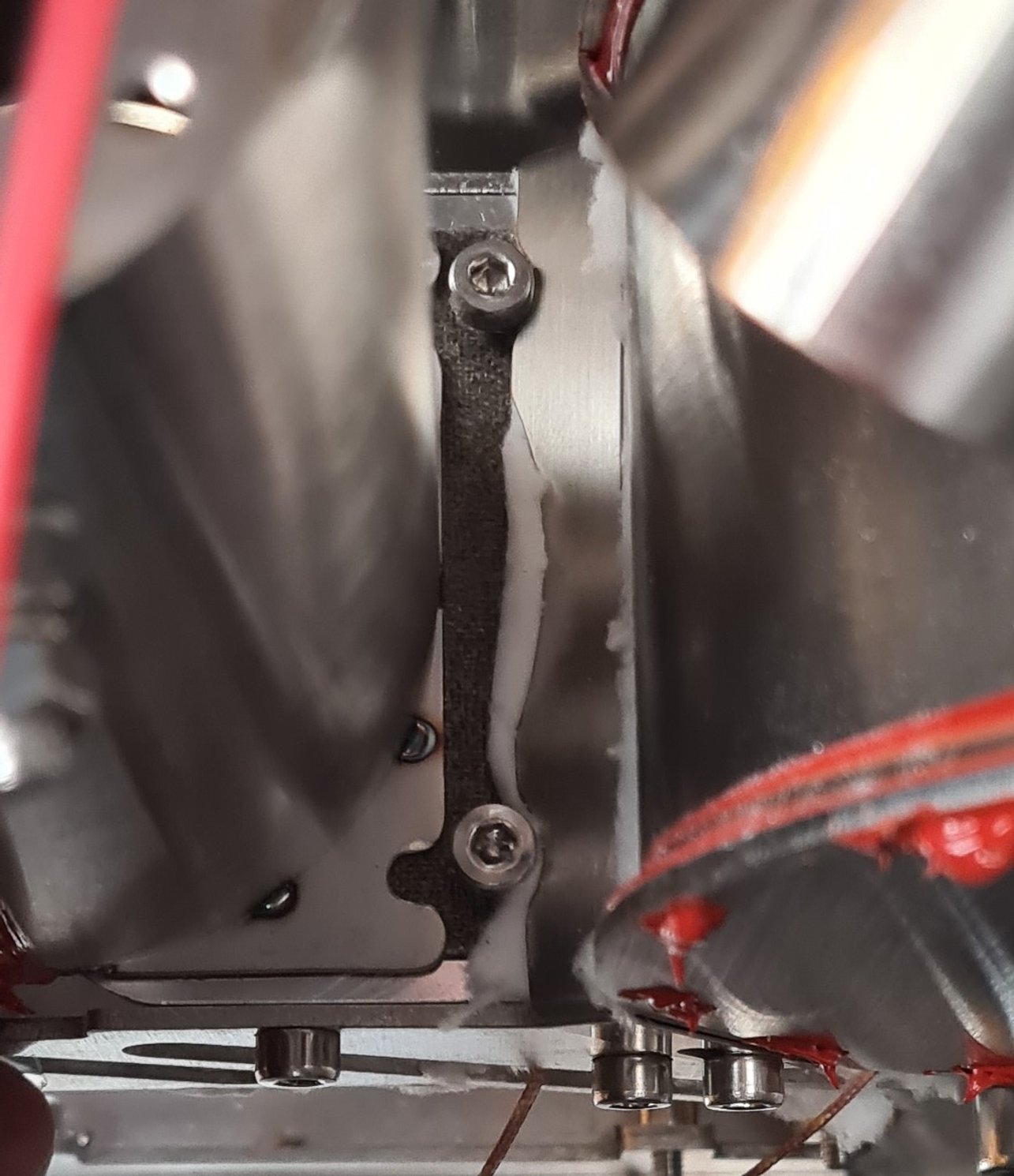
With a long 3-millimeter hexagonal key, loosen (not remove) the bolt sitting at the bottom of the housing.

Close view of the bolt inside the housing.
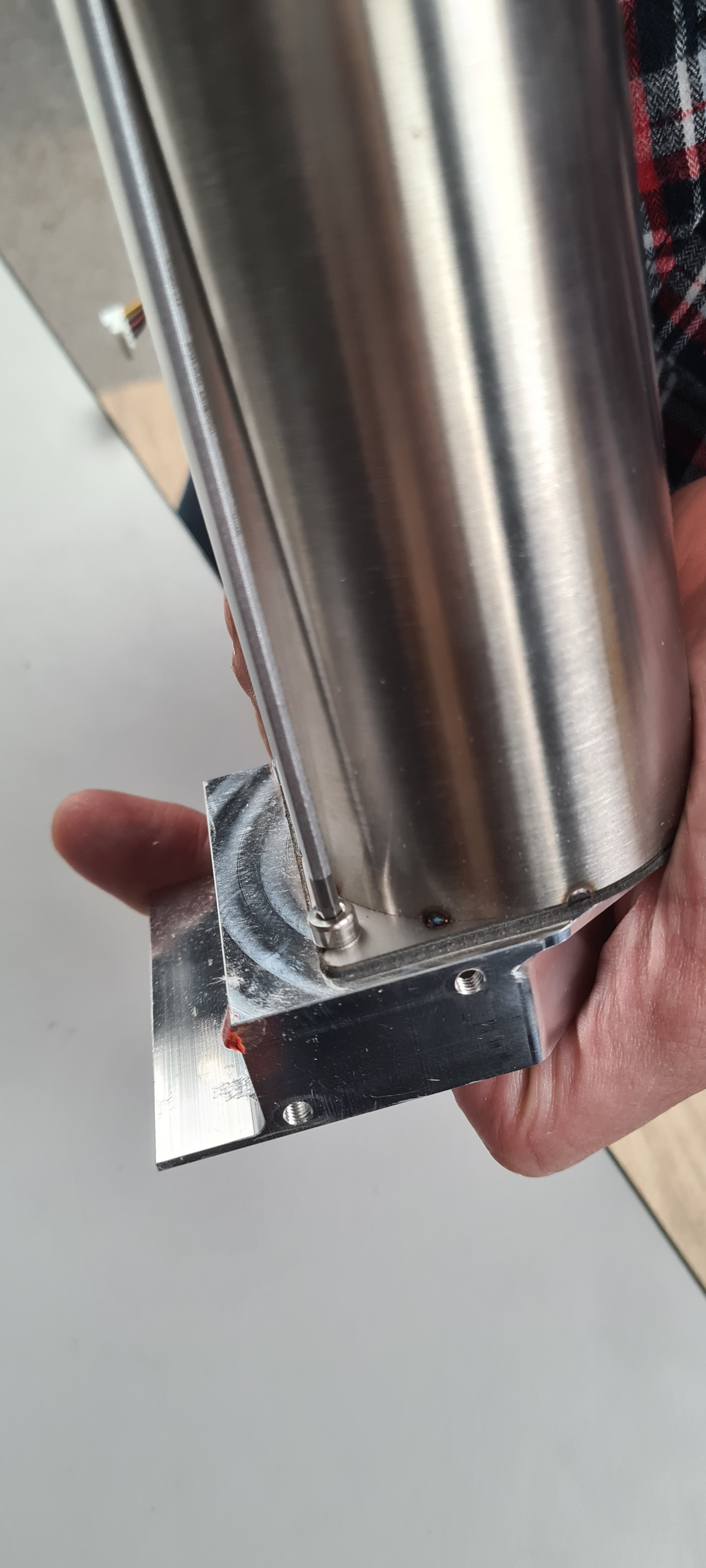
Loosen the two bolts outside the housing, connecting the heating element housing to the inlet housing we are switching out.

Leave the bolts loose like this, do not remove them yet.
Slide the housing away from the two front bolts.
Slide the housing away from the two bolts; now, the housing is free to be removed. Pull the housing upwards to remove it.
14. Remove the old inlet housing and install the new one with the inlet temperature.

Remove the mica tube by pulling it out.

Undo the three bolts and remove them.

Remove the spacer from the old inlet housing.

Install the spacer on the new inlet housing by leaving all three screws loosely done.

Leave space between the bolts and the housing.

Next, insert the k-type sensor through this gap.
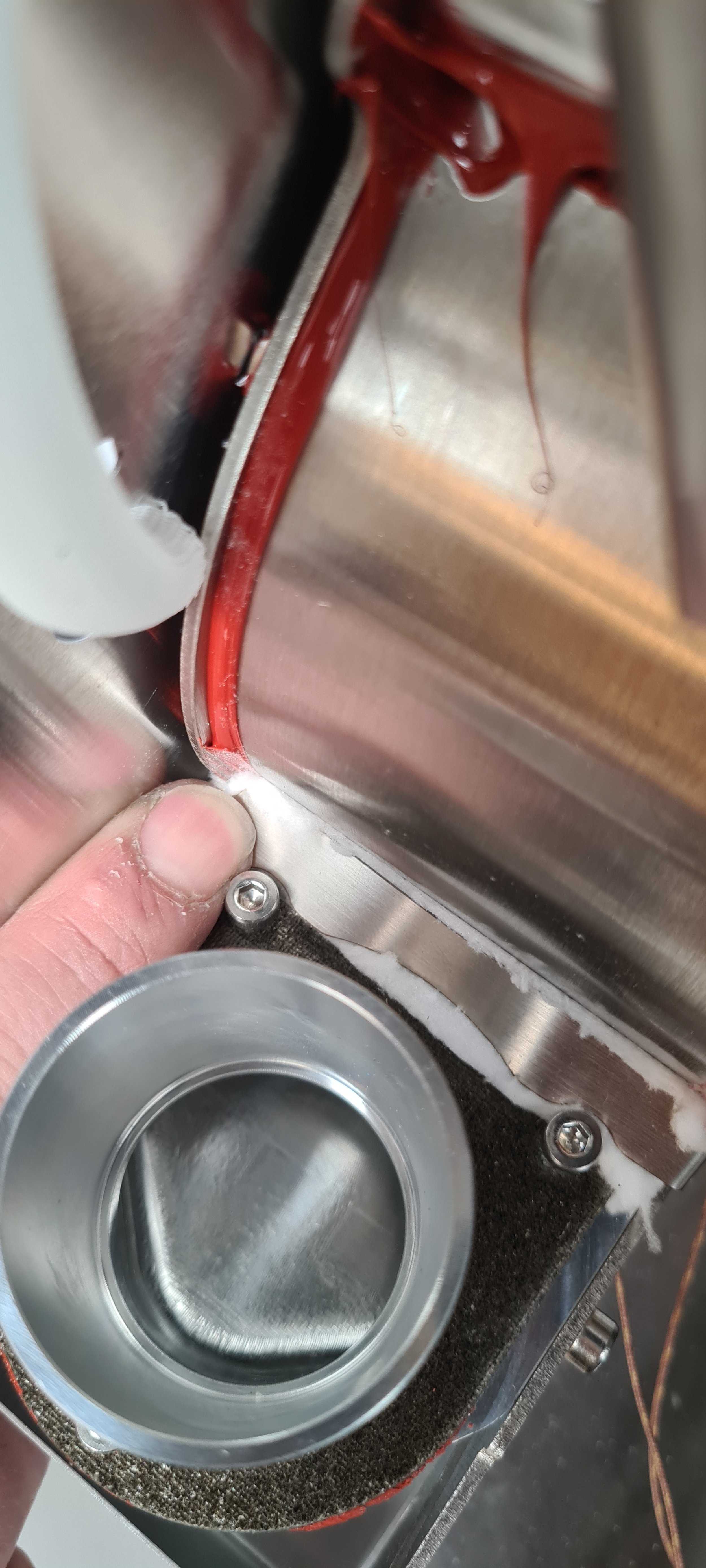
Insert the new inlet housing. Push the housing towards the drum.

Try to minimize the gap between the housing and the drum.
Make sure the holes of the inlet housing are aligned like in the photos below:


Insert the six bolts but don’t tighten them yet.

Use a 3-millimeter hex key to insert all six bolts loosely.

Leave the bolts loose like this.
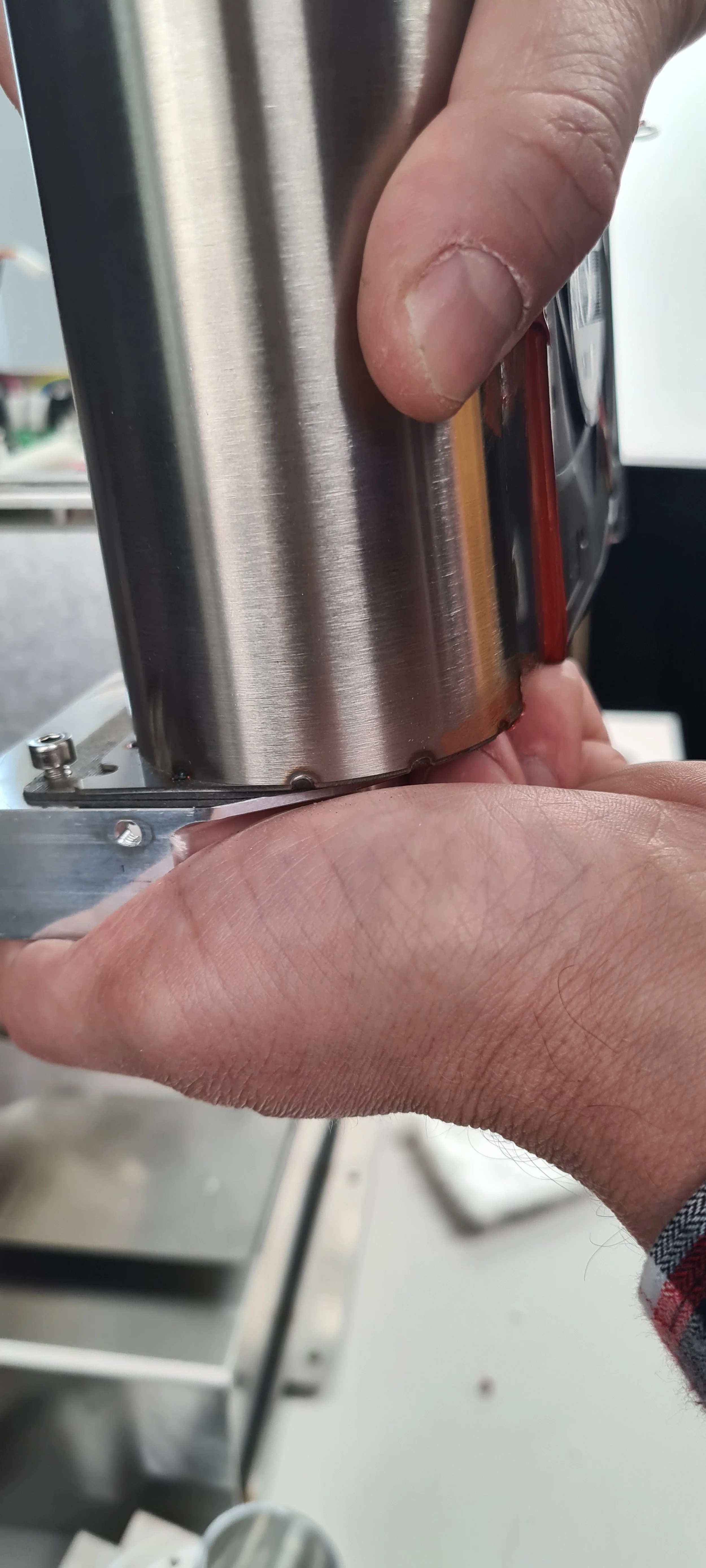
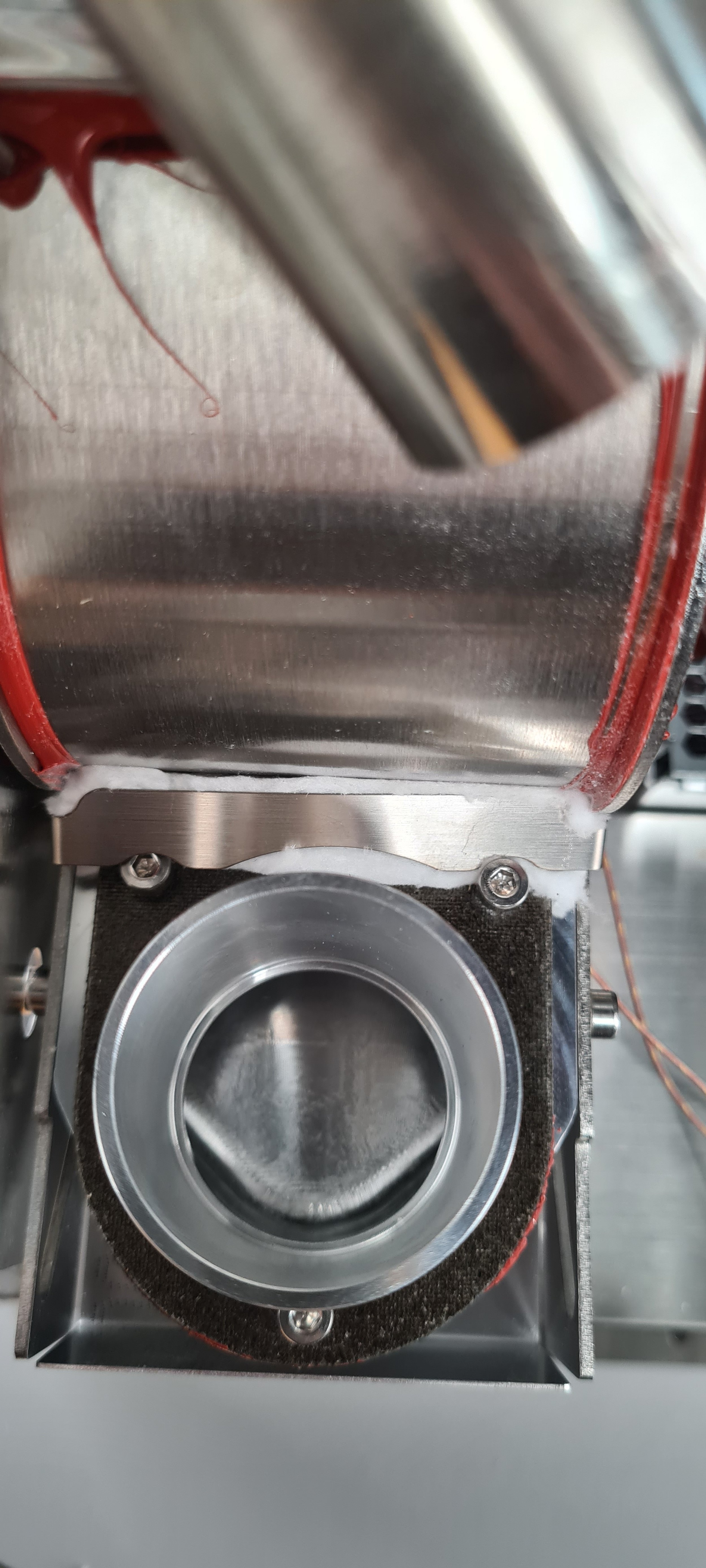
Push the inlet housing towards the drum, closing any gaps between the two.

Incorrect placement of inlet housing, notice the gap.

The inlet housing should be tightly pushed into the drum, like in the photo above.
Tighten the four bolts connected to the inlet housing and insert the small piece of super wool we removed initially. Leave the remaining two bolts loose.


Make sure the super wool doesn’t cover the bolts.
Insert the super wool bracket:

Make sure the bracket is installed correctly on the two remaining loose bolts.

Push down on the bracket and tighten the bolt.
Incorrect installment of the bracket. The bracket should not cover the bolts.
Correct installment of the bracket.

Push down the bracket on the left side and tighten the final bolt.

Insert the last piece of super wool by pushing the bracket downwards and inserting the super wool under the inlet housing.
Make sure to push the wool properly, so there is no gap, as shown in the photos below.

Too much of a gap.

Correct insertion of super wool where the gap is as closed as it can be.
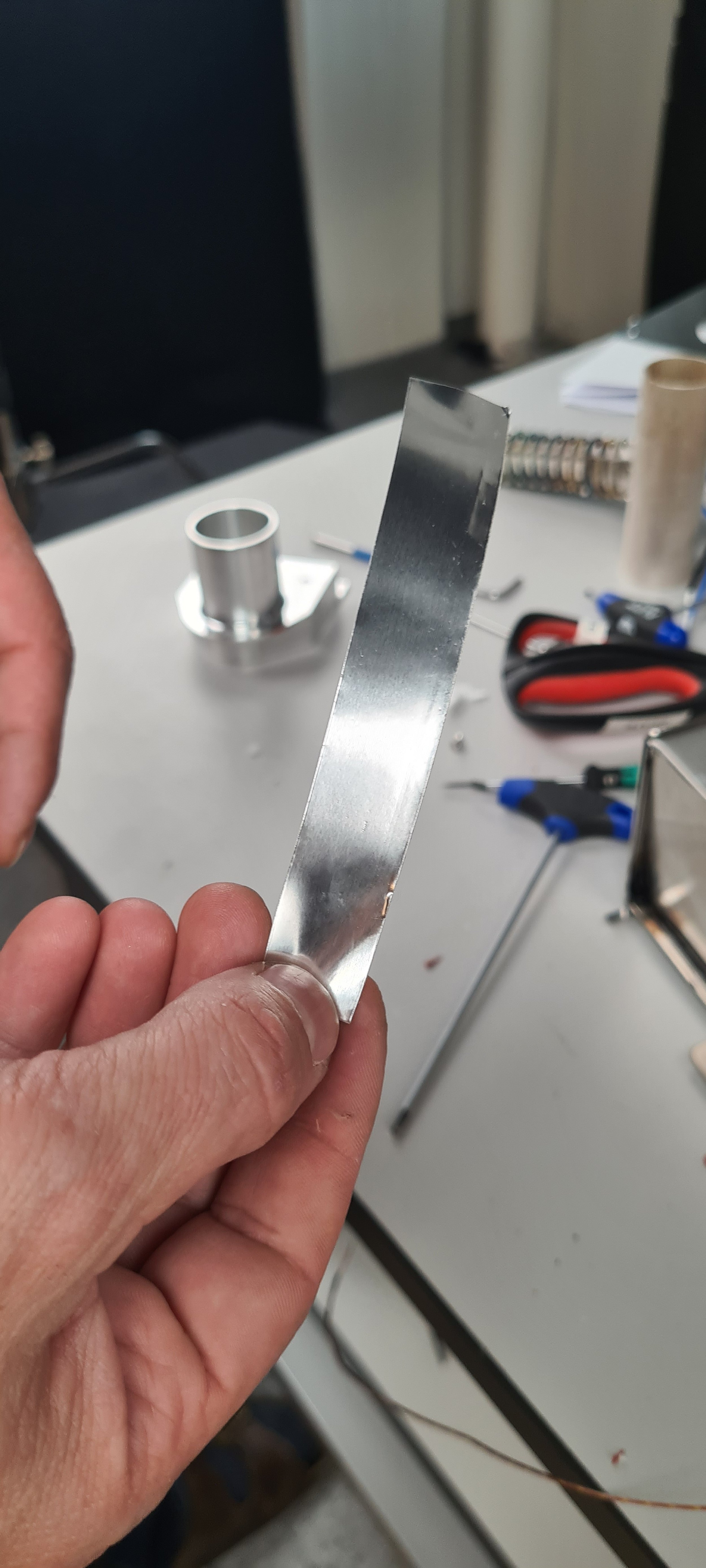
Find a piece of aluminium tape.

Install the tape as in the photo above, ensuring the brackets are firmly closed together.
15. Install the rest of the heating system.

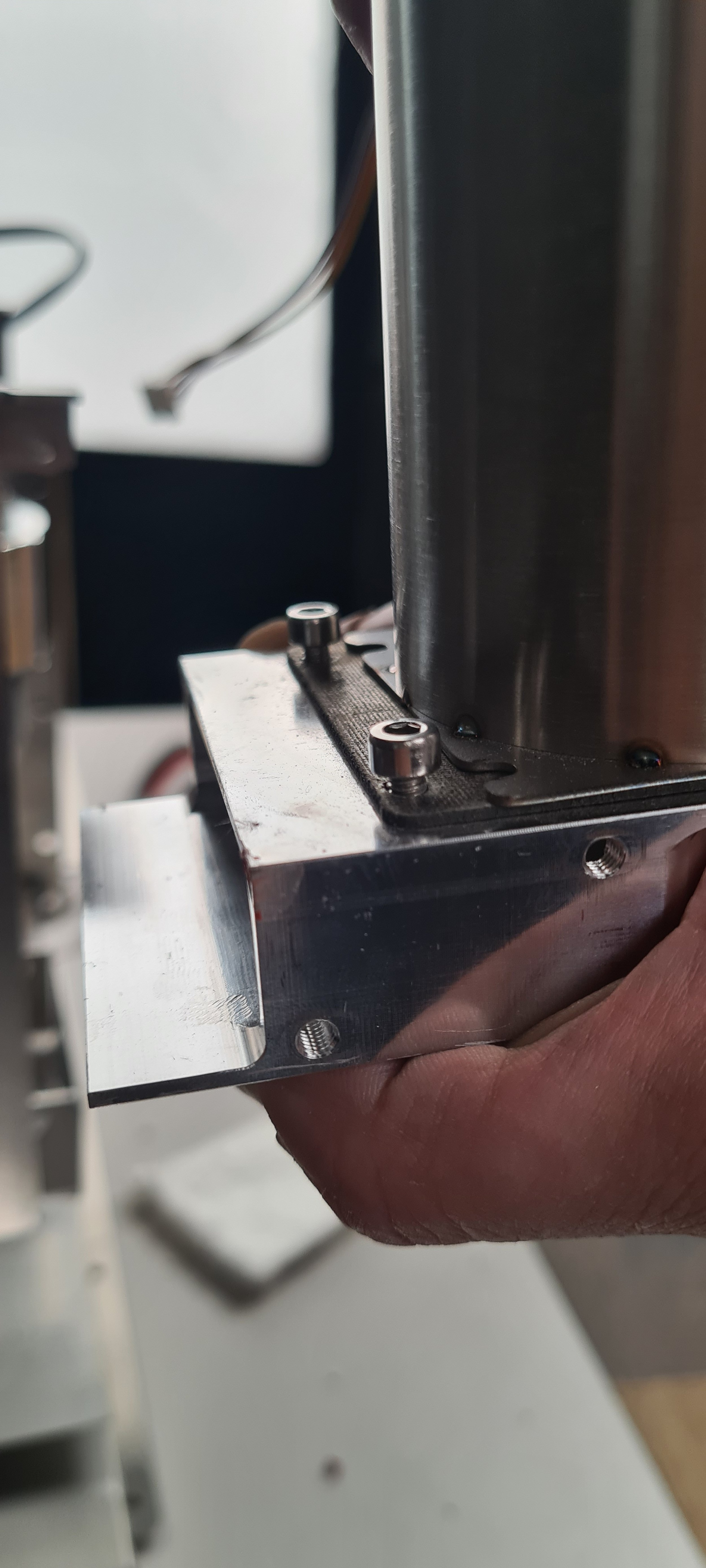
Slide the heating system on top of the new inlet housing.

As seen from above, you should position the heating element housing like this. You want to be able to slide the housing around the bolts.

How it looks inside after you’ve slid the housing into place.
How it should look on the outside before sliding the housing into place.

How it should look like after sliding the housing into place.

Tighten the screw on the inside..

And the two on the outside.

Insert the mica tube.

Use two fingers to firmly push the mica tube in place, making sure it’s pushed all the down.
Insert the heating element and tighten the two bolts.

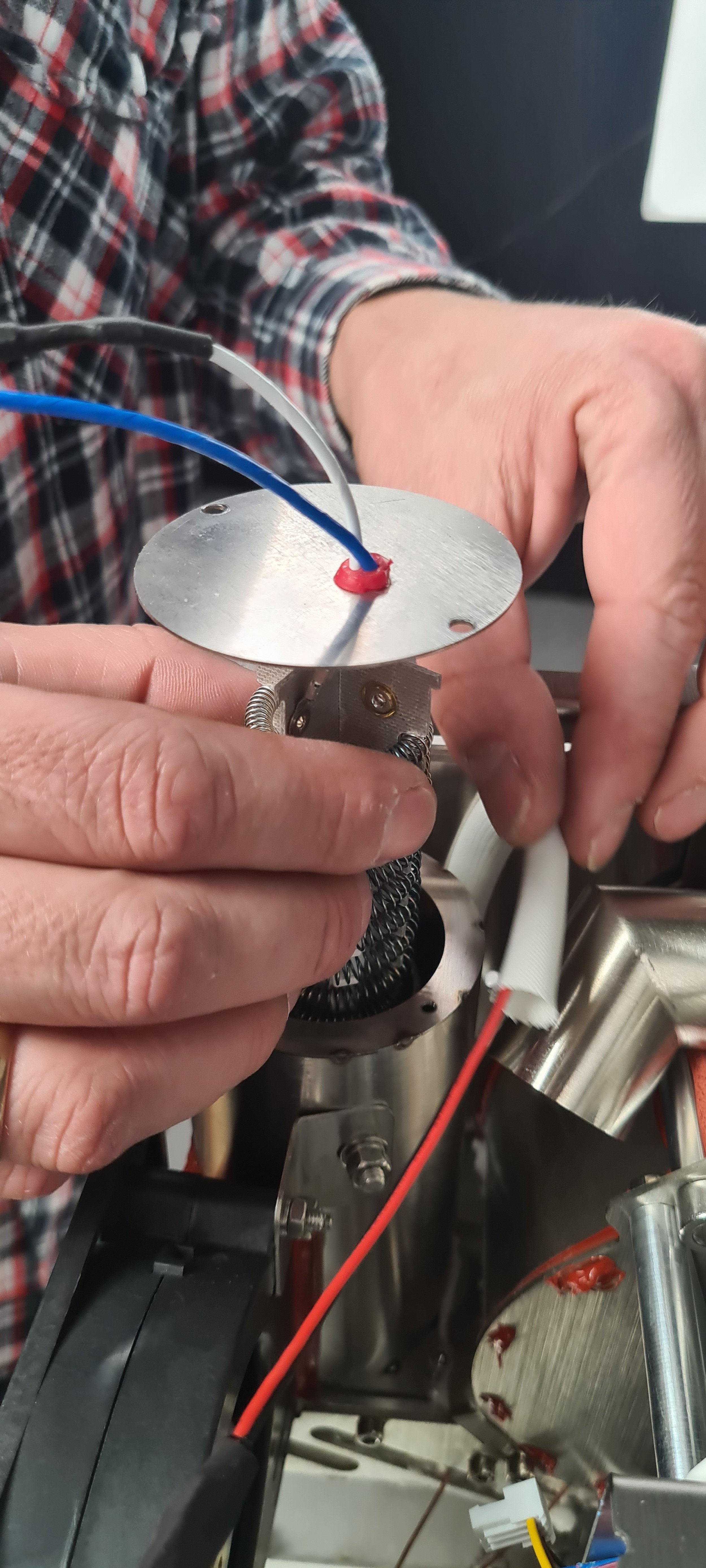
Make sure the orientation of the heating element is correct. The red rubber component should be closer to the PCB.
16. Connect all the cables:
Connect the heating element to the wago connectors.

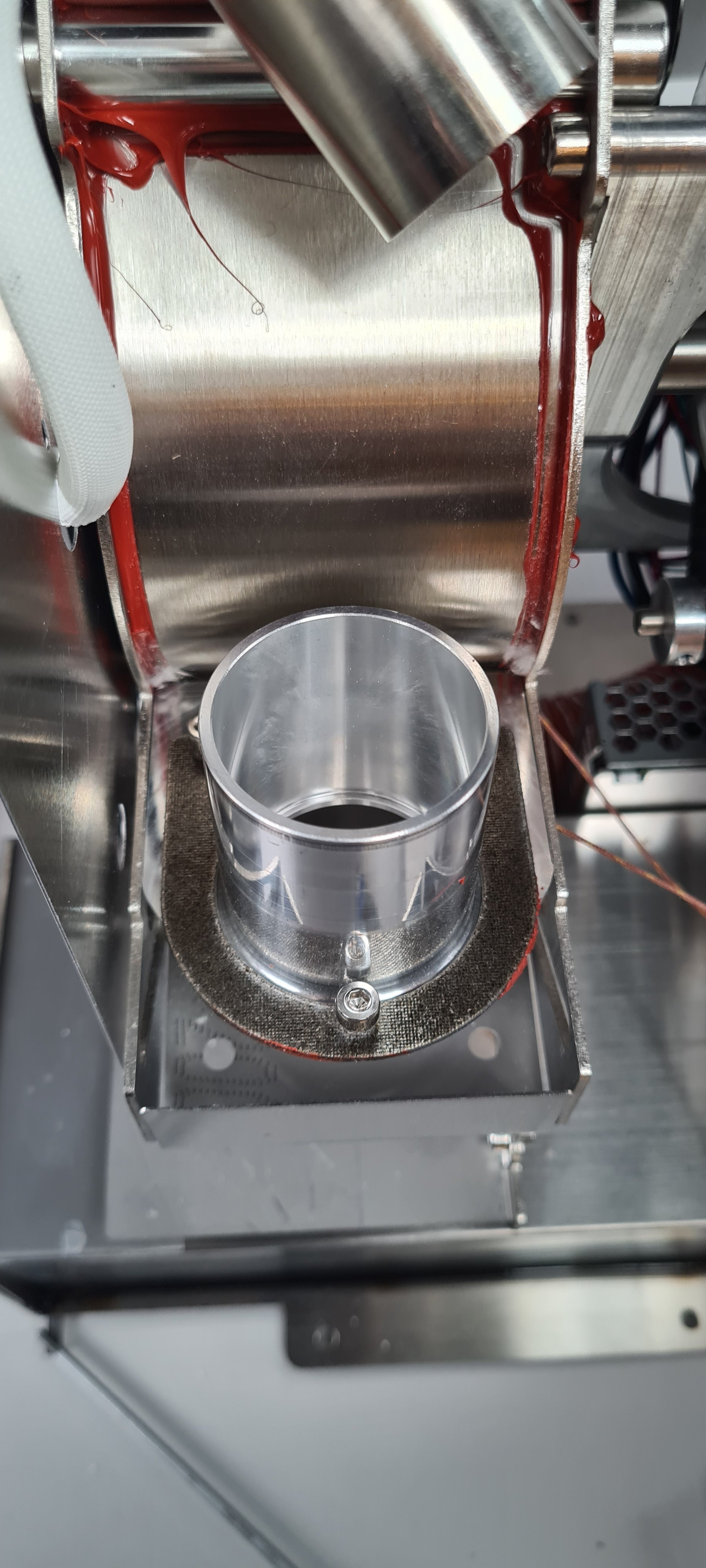
Install the orange hose before proceeding with the k-type sensors. Make sure it’s properly on, and there is no gap.

Ensure the hose is pushed correctly on the opening to the chaff separator. Look at the images below for reference.

This is too much of a gap.

Push the hose as far on the opening as you can.
16a. Install the drum temperature sensor:

Find the two k-type sensors and pull them out towards you, so they are easily available; the inlet temperature sensor will be marked with black tape so you can easily recognize it.
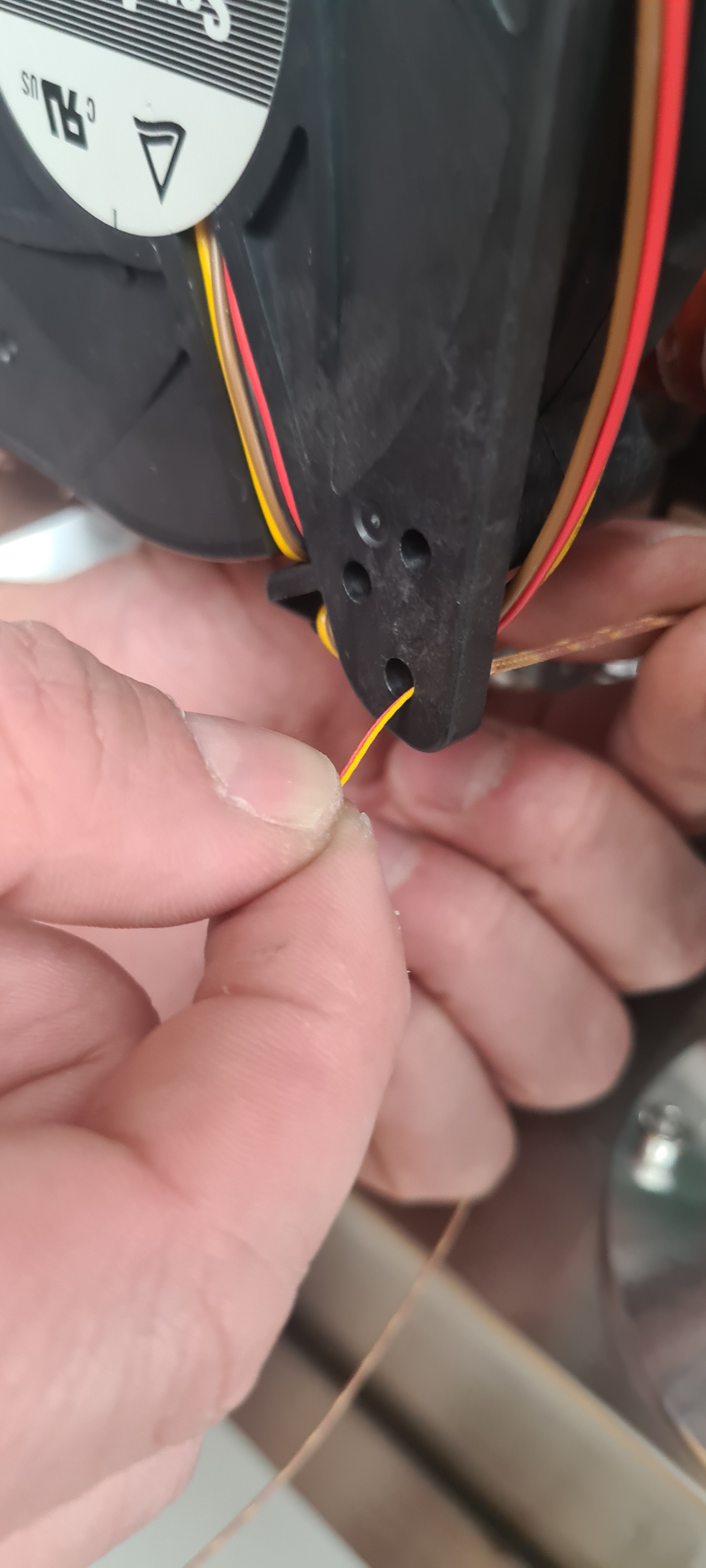
Pull the drum temperature sensor through the bottom hole of the heater fan.

Then pull it through the top hole of the heater fan.

Pull the sensor entirely through the top hole, but make sure it’s not so tight that it might damage the cable.

Make a note of the color code on the sensor. Yellow is positive; red is negative.
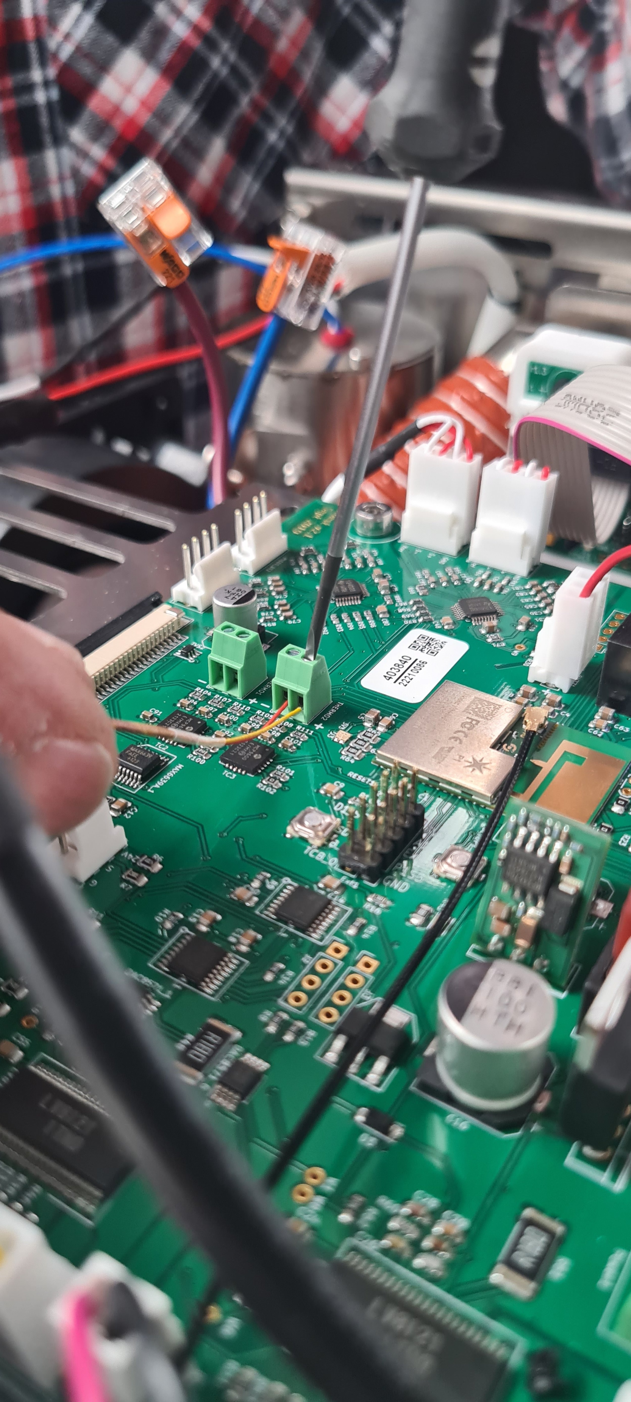
You should install the drum temperature in the screw terminal shown the in the photo. Make a note of which terminal entrance is the positive and negative one. Make sure the hole is completely open before inserting the wires. Tighten and make sure the wires are not loose and can slip out.

The cable can be positioned between the LED light and the heater fan component.
16b. Install the inlet temperature sensor:

Pull the inlet temperature sensor through the bottom hole.

And then through the top hole the same way as with the drum temperature sensor.
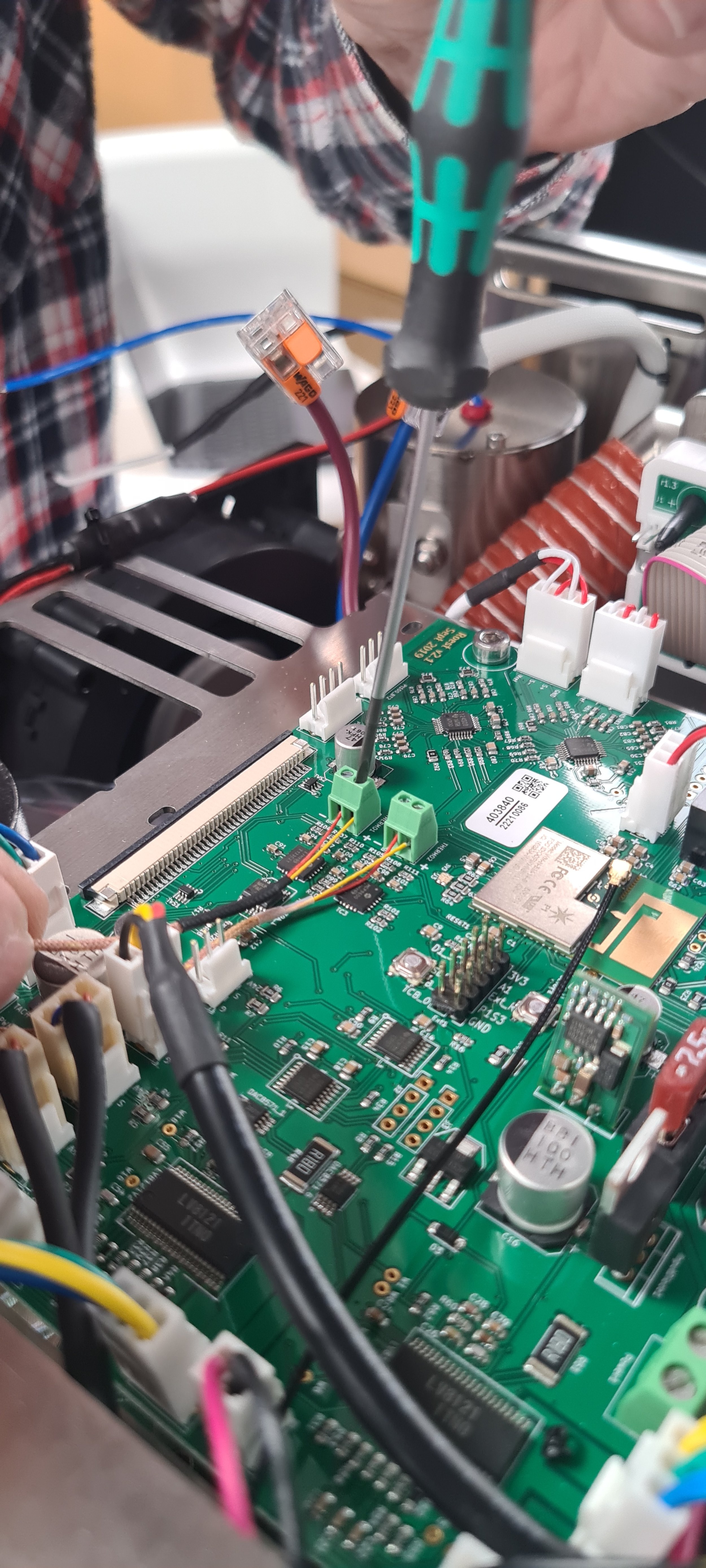
Install the inlet temperature sensor in the other screw terminal. As with the drum temperature sensor, yellow is positive, and red is negative. Again, make sure the terminals are completely open before inserting the cables. Tighten, and make sure none of the wires can slip out.
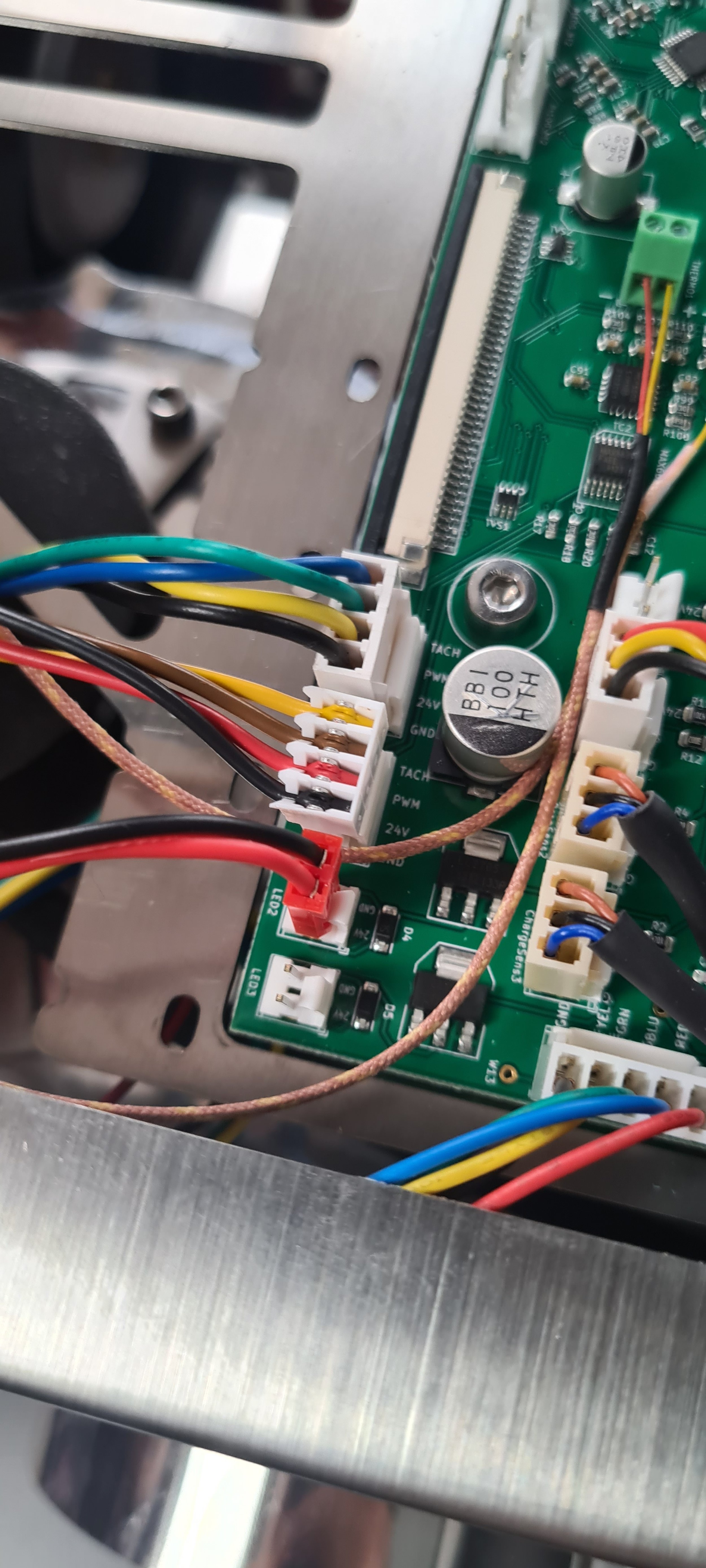
The cable can be left on the side, as shown in the image above.
17. Connect the heater fan to the PCB:

